Hi,
Here is a low cost wireless cellphone charger which is created by me as a part of my 12th standard project.
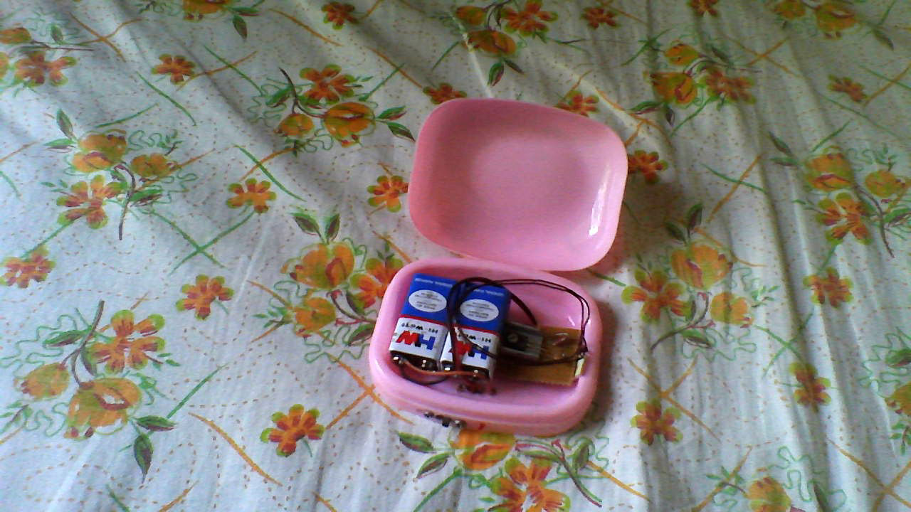
The above picture the inner view of the transmitter circuit that I enclosed in a small plastic box. Its cover is closed and the cellphone need to be charged is placed above it. I used two 9V PP3 type battery parallel as a power source to transmitter circuit. You can use a suitable DC source ranging from 9V-12V, 500mA either from a battery or from an AC adapter.
The components in transmitter side is only 3 capacitors, 1 transistor and 1 resistor. It is a very simple circuit that works on the principle of resonant inductive coupling. The power in the transmitter is picked by the copper loop in the receiver which is fixed in the cellphone. I made this circuit only for demonstration purpose, but you can use it whatever you like. It can charge upto 2 cellphones simultaneously at the same time. I charged a Nokia 7610 and which was successful.
Download circuit diagram for transmitter and receiver from Here: